
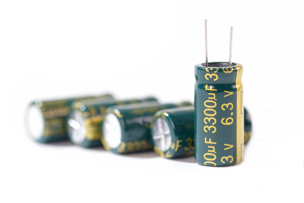
Capacitor In Series Vs. Parallel: A Closer Look
Quick Summary
Mica capacitors behave differently in series and parallel because each layout changes total capacitance, voltage behavior, and circuit response. Series arrangements reduce total capacitance and divide voltage across the connected parts, while parallel arrangements increase total capacitance and keep the same voltage across each branch. For RF, broadcast, defense, wind, solar, and high-voltage systems, proper selection depends on the full requirement, including rating, tolerance, fit, frequency behavior, and direct replacement compatibility.
Mica capacitors are common components in circuit boards, RF systems, broadcast equipment, power systems, and other electrical applications. Their job may seem straightforward at first, but the way they are connected can change how they behave in a circuit. That is where the comparison of capacitor in series vs parallel becomes important. Does a mica capacitor function differently when it is placed in a series arrangement compared with a parallel arrangement? The answer depends on capacitance, voltage, load, and circuit goals.
Let’s take a closer look at how both setups work and why the difference matters.
Why Circuit Layout Changes Mica Capacitor Performance
A mica capacitor responds to the circuit around it, so placement can change the result you see at the equipment level. Series and parallel layouts create different electrical relationships, even when the individual mica capacitors have the same printed value. Once parts are connected together, the circuit reads them as one equivalent value, and that value depends on the connection pattern. Voltage stress, charge behavior, impedance, and load response can also shift based on the arrangement.
For RF and high-voltage work, this difference can affect tuning accuracy, power handling, and replacement decisions. A circuit board, transmitter, power supply, or industrial control system may call for a layout because the design needs a specific response. That is why engineers and technical enthusiasts often look beyond the part number alone. Connection style, rating, tolerance, and operating conditions all shape how a mica capacitor bank performs in service under real electrical operating demand.
How Mica Capacitors Behave in Series
Placed end to end, each unit becomes part of a single path through the circuit. In this arrangement, total capacitance becomes lower than the value of any individual mica capacitor in the string. That can surprise buyers who expect added parts to create a higher value. Instead, a series setup reduces the equivalent capacitance because the spacing effect between conductive plates is increased across the connected group. The standard formula is:
1/Ctotal = 1/C1 + 1/C2 + 1/C3
Voltage behavior also changes in a series arrangement. The total applied voltage is divided across the connected mica capacitors, which is one reason series connections appear in high-voltage discussions. However, voltage division depends on value, tolerance, leakage, and operating conditions. A mismatched setup may place more stress on one part than expected. For RF, broadcast, and power applications, series behavior should be evaluated through the full circuit requirement, not through capacitance value alone.
How Mica Capacitors Behave in Parallel
Connected across the same two points, each unit shares the same voltage while contributing to the total capacitance. A parallel arrangement adds mica capacitor values together, which makes this layout useful when a circuit needs a higher combined value. Two 500 pF mica capacitors in parallel create 1,000 pF total capacitance. Unlike a series string, the equivalent value rises as more units are added across the same nodes. The standard formula is:
Ctotal = C1 + C2 + C3
Practical behavior still depends on more than the arithmetic. Current sharing, lead length, physical layout, tolerance, temperature, and RF frequency can all affect how the group performs. In tuned circuits, broadcast equipment, and high-voltage systems, a parallel bank may help reach a required value while keeping voltage equal across each branch. Buyers still need to match the mica capacitor type, rating, mounting style, and application demands, especially when replacing an existing CDM part in equipment that already has a defined electrical design and a clear service expectation.
How Each Setup Affects Capacitance, Voltage, and Load
Looking at the circuit as a whole helps show why the two arrangements produce different results. A series group lowers total capacitance and divides the applied voltage across the connected mica capacitors. A parallel group raises total capacitance and places the same voltage across each branch. Those differences affect how the circuit stores energy, responds to signal conditions, and manages electrical stress during operation. In RF work, the effect can become more noticeable because capacitive reactance changes as frequency changes.
Load behavior also depends on the equipment, layout, and operating environment. A series arrangement may fit a design that needs a lower equivalent value or a specific voltage distribution. A parallel arrangement may fit a design that needs more capacitance or a different current profile. However, replacement decisions should account for capacitance, voltage rating, RF current, tolerance, temperature stability, and physical fit. A mica capacitor bank must match the circuit’s electrical intent, especially in transmitters, power systems, industrial controls, renewable energy equipment, and other technical applications where stability matters under demanding electrical and environmental conditions over extended service periods reliably.
Why Usage Depends on the Circuit Goal
A proper choice starts with the job the circuit needs to perform. Some designs need a lower equivalent value, while others need a higher combined value. Some systems place more attention on voltage distribution, while others place more attention on current behavior, tuning response, or replacement compatibility. That is why usage is tied to the circuit goal rather than the connection style alone. A series layout and a parallel layout can both be correct, depending on the electrical target.
For broadcast transmitters, RF equipment, defense systems, wind systems, solar equipment, and industrial applications, a mica capacitor may need to match an existing design with very little room for variation. A direct replacement decision often involves the original CDM specification, mounting style, voltage rating, and frequency behavior. You may also need to confirm whether the circuit was designed around a series value, a parallel value, or a complete bank arrangement before sourcing the part. This context helps prevent value mismatches that could affect performance, reliability, equipment uptime, or planned maintenance schedules.
What RF and High-Voltage Factors Should You Consider
Before sourcing a replacement, you need to look at the full electrical and mechanical requirement. Capacitance value is only one part of the decision, especially in RF and high-voltage equipment. Voltage rating, RF current rating, tolerance, temperature stability, frequency behavior, case size, terminal style, and mounting fit can all influence performance. A mica capacitor that matches the printed value may still be wrong if the rating, construction, or physical format does not match the original design. Existing CDM applications often require direct replacement matching because the surrounding circuit was built around a defined specification. For technical buyers, that means the best choice comes from confirming the complete part requirement before placing an order or approving a substitution for service, maintenance, or production work with proper confidence, fewer sourcing delays, stronger application fit, and reliable performance.
Make The Right Mica Capacitor Choice
A series or parallel arrangement can change how a circuit reaches its required value, handles voltage, and responds under real operating load. That makes the connection style more than a layout detail, especially in RF, broadcast, defense, wind, solar, and high-voltage systems. Careful matching helps protect performance, supports smoother maintenance decisions, and gives your team clearer confidence during sourcing, repair planning, or equipment review.
At Commercial Radio Company, we help technical buyers source CDM mica transmitting capacitors and CDM direct replacement mica capacitors for demanding applications. We also supply RF contactors for systems that require dependable component support. Our wide inventory, specialized experience, same-day shipping, and direct purchasing model help you reduce sourcing delays and buy directly from a trusted stocking distributor with legacy leadership and practical product knowledge.
Contact us by phone or email for current availability, part matching support, or order assistance today. We are ready to help you find the right mica capacitors for your application with responsive support.
FAQs
Mica capacitors in series reduce the total capacitance and divide voltage across the connected units. Mica capacitors in parallel increase the total capacitance while keeping the same voltage across each branch. This difference matters because each arrangement changes how a circuit stores energy, handles load, and responds under operating conditions.
A series arrangement may be used when a design needs a lower equivalent capacitance value or a specific voltage distribution across multiple mica capacitors. This setup is common in high-voltage discussions, but proper matching is important. Value, tolerance, leakage, voltage rating, and operating conditions can all affect performance.
RF and broadcast systems often depend on stable capacitance, voltage rating, RF current rating, frequency behavior, and physical fit. A mica capacitor may have the right printed value but still be wrong for the application. Direct replacement matching helps protect tuning accuracy, reliability, and equipment performance.
